Piping Diagram Valve Symbols . A piping and instrumentation diagram (p&id) includes symbols for ball valves, communication lines, vessels and other components. A valve regulates, directs, or controls the flow of a fluid by opening, closing, or partially obstructing passageways in a piping. Knowing the valve symbols is essential for you to understand the piping and instrumentation diagram. We have two main types of valve symbols used in the p&id. Lines that indicate the direction of flow, along with specifications about the pipe size, material, and number. A piping and instrumentation diagram (p&id) is a graphic representation of a process system that includes the piping,. Here’s how to read a p&id. Piping and instrumentation diagrams (p&ids) use specific symbols to show the connectivity of equipment, sensors, and valves in a control.
from assuredautomation.com
A piping and instrumentation diagram (p&id) is a graphic representation of a process system that includes the piping,. Here’s how to read a p&id. Lines that indicate the direction of flow, along with specifications about the pipe size, material, and number. We have two main types of valve symbols used in the p&id. Piping and instrumentation diagrams (p&ids) use specific symbols to show the connectivity of equipment, sensors, and valves in a control. A valve regulates, directs, or controls the flow of a fluid by opening, closing, or partially obstructing passageways in a piping. A piping and instrumentation diagram (p&id) includes symbols for ball valves, communication lines, vessels and other components. Knowing the valve symbols is essential for you to understand the piping and instrumentation diagram.
P&IDs (Piping & Instrumentation Diagrams) and P&ID Valve Symbol Library
Piping Diagram Valve Symbols Here’s how to read a p&id. A piping and instrumentation diagram (p&id) includes symbols for ball valves, communication lines, vessels and other components. A piping and instrumentation diagram (p&id) is a graphic representation of a process system that includes the piping,. Knowing the valve symbols is essential for you to understand the piping and instrumentation diagram. Here’s how to read a p&id. Lines that indicate the direction of flow, along with specifications about the pipe size, material, and number. Piping and instrumentation diagrams (p&ids) use specific symbols to show the connectivity of equipment, sensors, and valves in a control. We have two main types of valve symbols used in the p&id. A valve regulates, directs, or controls the flow of a fluid by opening, closing, or partially obstructing passageways in a piping.
From engineeringdiscoveries.com
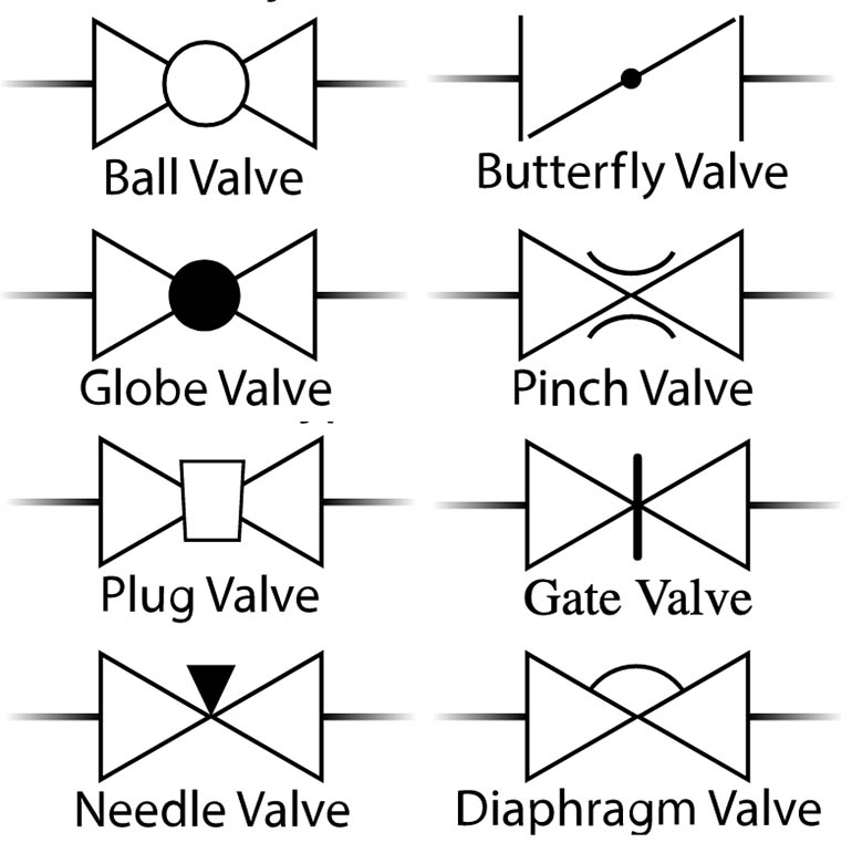
Types Of Valves, Their Functions And Symbols Engineering Discoveries Piping Diagram Valve Symbols A valve regulates, directs, or controls the flow of a fluid by opening, closing, or partially obstructing passageways in a piping. Lines that indicate the direction of flow, along with specifications about the pipe size, material, and number. We have two main types of valve symbols used in the p&id. A piping and instrumentation diagram (p&id) is a graphic representation. Piping Diagram Valve Symbols.
From pipingandinstrumentationdiagram.blogspot.com
P&ID Process Diagram, Piping, Symbol, Abbreviation, Equipment, Pump Piping Diagram Valve Symbols A valve regulates, directs, or controls the flow of a fluid by opening, closing, or partially obstructing passageways in a piping. We have two main types of valve symbols used in the p&id. A piping and instrumentation diagram (p&id) includes symbols for ball valves, communication lines, vessels and other components. Knowing the valve symbols is essential for you to understand. Piping Diagram Valve Symbols.
From diagramlibraryfis.z5.web.core.windows.net
Piping Schematic Valve Symbols Piping Diagram Valve Symbols A valve regulates, directs, or controls the flow of a fluid by opening, closing, or partially obstructing passageways in a piping. Here’s how to read a p&id. We have two main types of valve symbols used in the p&id. A piping and instrumentation diagram (p&id) includes symbols for ball valves, communication lines, vessels and other components. A piping and instrumentation. Piping Diagram Valve Symbols.
From www.allaboutpiping.com
What is Piping Isometric drawing? How to Read Piping Drawing? ALL Piping Diagram Valve Symbols A valve regulates, directs, or controls the flow of a fluid by opening, closing, or partially obstructing passageways in a piping. Lines that indicate the direction of flow, along with specifications about the pipe size, material, and number. Knowing the valve symbols is essential for you to understand the piping and instrumentation diagram. We have two main types of valve. Piping Diagram Valve Symbols.
From manualdbcopolymer.z22.web.core.windows.net
Needle Valve P&id Symbol Piping Diagram Valve Symbols Knowing the valve symbols is essential for you to understand the piping and instrumentation diagram. Lines that indicate the direction of flow, along with specifications about the pipe size, material, and number. Piping and instrumentation diagrams (p&ids) use specific symbols to show the connectivity of equipment, sensors, and valves in a control. A valve regulates, directs, or controls the flow. Piping Diagram Valve Symbols.
From schematiclibpraecox99.z13.web.core.windows.net
Piping Schematic Valve Symbols Piping Diagram Valve Symbols Knowing the valve symbols is essential for you to understand the piping and instrumentation diagram. A piping and instrumentation diagram (p&id) includes symbols for ball valves, communication lines, vessels and other components. Here’s how to read a p&id. Lines that indicate the direction of flow, along with specifications about the pipe size, material, and number. We have two main types. Piping Diagram Valve Symbols.
From schematicpartkaraoke.z14.web.core.windows.net
Piping Instrumentation Diagram Symbols Piping Diagram Valve Symbols Here’s how to read a p&id. Piping and instrumentation diagrams (p&ids) use specific symbols to show the connectivity of equipment, sensors, and valves in a control. We have two main types of valve symbols used in the p&id. A valve regulates, directs, or controls the flow of a fluid by opening, closing, or partially obstructing passageways in a piping. A. Piping Diagram Valve Symbols.
From diagramlistliebig.z13.web.core.windows.net
Piping Schematic Valve Symbols Piping Diagram Valve Symbols We have two main types of valve symbols used in the p&id. A piping and instrumentation diagram (p&id) includes symbols for ball valves, communication lines, vessels and other components. Here’s how to read a p&id. A piping and instrumentation diagram (p&id) is a graphic representation of a process system that includes the piping,. Lines that indicate the direction of flow,. Piping Diagram Valve Symbols.
From pipingandinstrumentationdiagram.blogspot.com
P&ID Process Diagram, Piping, Symbol, Abbreviation, Equipment, Pump Piping Diagram Valve Symbols Piping and instrumentation diagrams (p&ids) use specific symbols to show the connectivity of equipment, sensors, and valves in a control. We have two main types of valve symbols used in the p&id. Here’s how to read a p&id. A valve regulates, directs, or controls the flow of a fluid by opening, closing, or partially obstructing passageways in a piping. Lines. Piping Diagram Valve Symbols.
From forumautomation.com
Piping & Instrumentation Diagrams Tutorials on Pressure Control Field Piping Diagram Valve Symbols We have two main types of valve symbols used in the p&id. Knowing the valve symbols is essential for you to understand the piping and instrumentation diagram. A valve regulates, directs, or controls the flow of a fluid by opening, closing, or partially obstructing passageways in a piping. Lines that indicate the direction of flow, along with specifications about the. Piping Diagram Valve Symbols.
From mungfali.com
Piping Diagram Symbols Valves Piping Diagram Valve Symbols A piping and instrumentation diagram (p&id) is a graphic representation of a process system that includes the piping,. We have two main types of valve symbols used in the p&id. A piping and instrumentation diagram (p&id) includes symbols for ball valves, communication lines, vessels and other components. Knowing the valve symbols is essential for you to understand the piping and. Piping Diagram Valve Symbols.
From me-resetsg.blogspot.com
Mechanical Engineering Classifications of Valves!! Piping Diagram Valve Symbols A valve regulates, directs, or controls the flow of a fluid by opening, closing, or partially obstructing passageways in a piping. A piping and instrumentation diagram (p&id) includes symbols for ball valves, communication lines, vessels and other components. Lines that indicate the direction of flow, along with specifications about the pipe size, material, and number. Here’s how to read a. Piping Diagram Valve Symbols.
From www.instrumentationtoolbox.com
Common Process Equipment Symbols Used in Developing Process Flow Piping Diagram Valve Symbols Knowing the valve symbols is essential for you to understand the piping and instrumentation diagram. A piping and instrumentation diagram (p&id) is a graphic representation of a process system that includes the piping,. Here’s how to read a p&id. A piping and instrumentation diagram (p&id) includes symbols for ball valves, communication lines, vessels and other components. We have two main. Piping Diagram Valve Symbols.
From schematicpartkaraoke.z14.web.core.windows.net
Piping Diagram Symbols Piping Diagram Valve Symbols A valve regulates, directs, or controls the flow of a fluid by opening, closing, or partially obstructing passageways in a piping. Piping and instrumentation diagrams (p&ids) use specific symbols to show the connectivity of equipment, sensors, and valves in a control. We have two main types of valve symbols used in the p&id. A piping and instrumentation diagram (p&id) is. Piping Diagram Valve Symbols.
From www.xhval.com
P&ID Valve Symbols How to read them on most XHVAL Piping Diagram Valve Symbols A piping and instrumentation diagram (p&id) includes symbols for ball valves, communication lines, vessels and other components. A piping and instrumentation diagram (p&id) is a graphic representation of a process system that includes the piping,. Here’s how to read a p&id. Lines that indicate the direction of flow, along with specifications about the pipe size, material, and number. Knowing the. Piping Diagram Valve Symbols.
From circuitengineforrad88.z13.web.core.windows.net
Piping Schematic Symbols Piping Diagram Valve Symbols A piping and instrumentation diagram (p&id) includes symbols for ball valves, communication lines, vessels and other components. A piping and instrumentation diagram (p&id) is a graphic representation of a process system that includes the piping,. Lines that indicate the direction of flow, along with specifications about the pipe size, material, and number. Here’s how to read a p&id. A valve. Piping Diagram Valve Symbols.
From mungfali.com
Piping Diagram Symbols Valves Piping Diagram Valve Symbols A piping and instrumentation diagram (p&id) includes symbols for ball valves, communication lines, vessels and other components. We have two main types of valve symbols used in the p&id. A piping and instrumentation diagram (p&id) is a graphic representation of a process system that includes the piping,. Piping and instrumentation diagrams (p&ids) use specific symbols to show the connectivity of. Piping Diagram Valve Symbols.
From mungfali.com
Piping Diagram Symbols Valves Piping Diagram Valve Symbols We have two main types of valve symbols used in the p&id. Here’s how to read a p&id. Piping and instrumentation diagrams (p&ids) use specific symbols to show the connectivity of equipment, sensors, and valves in a control. A piping and instrumentation diagram (p&id) includes symbols for ball valves, communication lines, vessels and other components. Lines that indicate the direction. Piping Diagram Valve Symbols.